My voltage regulator stopped working. I could watch my fuel gauge wave up and down by about half the scale with a period of about a minute. After a couple of weeks it stopped waving so much and stayed in the bottom quarter of the scale, no matter how much fuel was actually in the tank.
Obviously I had to fix this. The regulator on the clubman behind the steering wheel instruments is mounted on a fiberous board, about 1.5cm by 3cm with a metal can about 0.5cm deep crimped over it. The regulator pulls out of the instrument pack, where it is held simply by the three connectors. It is in the lower middle of the instrument pack and should be removable without removing the pack from its mounting brackets. If in doubt, use mirrors or contorsion acts to view the back of the instruments before levering anything off it, as not everything will take kindly to abuse from a screwdriver.
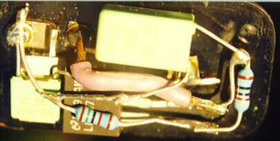
I removed all the (now non working) components from the regulator and left three pads where the connectors pass through the insulator base. I then scraped the crap off the the pads so that I could solder to them effectivly. Then I installed a modern voltage regulator, the LM317. This rather over exposed picture shows the final circuit. The green components are capactors, which probably aren't necessary, but since they fitted inside the case, and do stabilise the circuit, I put them in.
I epoxied the parts that I felt were going to short out to the metal casing when it was replaced. Of particular importance was it epoxy the voltage regulator itself to the backing insulator. The metal mounting tag is live (or grounded, I forget which) and it is very close to the ground (or output, as applicalble) on the left hand side of the picture.
The whole circuit cost me about NZ$7. The datasheet for the regulator is available at National Semiconductor.
My gauges are rock steady now and I would expect this circuit to last basically forever.